
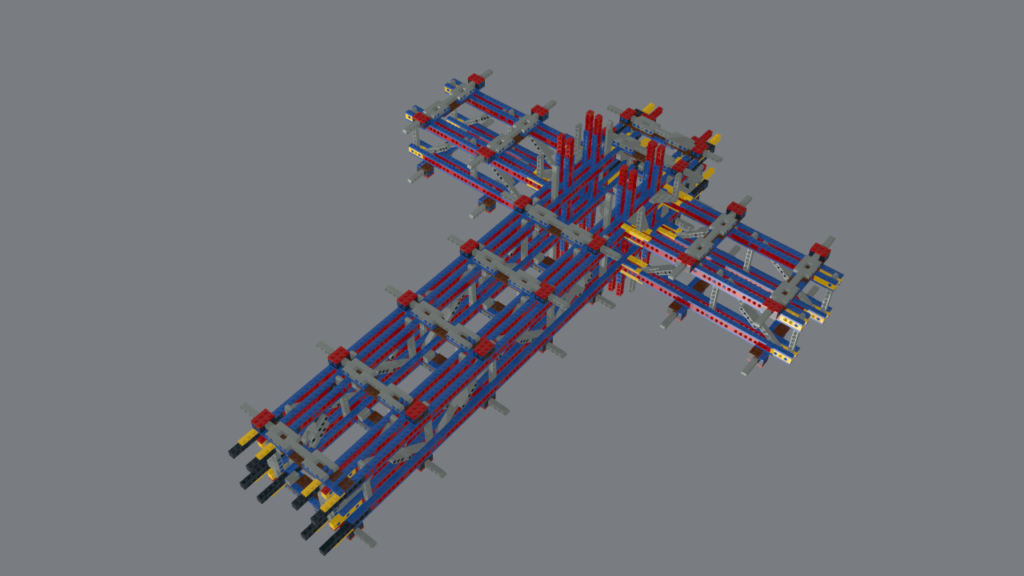
Here we are at Day 2. Todays focus will be taking the truss from Day 1, pairing it, assembling it with spacers and then adding the airlock corridors at the T-junction. This is a fairly simple build day. Four more truss sections (I pre-built the second main truss yesterday), the four the airlock corridor trusses and 22 spacers. These spacers join the truss sections together creating a corridor down the middle and they will also hold the “rings” over which the outer hull will be placed creating the cylindrical shape. Here is a LeoCAD rendering of the planned progress at the end of Day 2.
Overall, Day 2 went well. Only the usual issues like trying to find the right pieces and struggling to separate plates. One minor modification was to change the spacers on the two side airlock corridors. These corridors are constructed of two brick wide trusses as opposed to the three brick wide trusses of the main corridor. The side corridors are short and subject to much less load and stress than the main corridor. I adjusted the spacers slightly to better fit the top of the side corridor trusses.
The main corridor has to be strong as it will be trying rip itself apart upon final assembly. There is a span of about 1.5 m between the landing gears under the engines and the landing gears at the front of the main area of the ship which will have to support the weight of 10s of thousands of pieces along its axis. Another load is the counter-lever force from the engines at the back of the ship. The 11 engines will weigh about 60 pounds and will be counter balanced by the front of the ship. Between these two balanced loads, the main corridor will be trying to bend upwards. This is another reason why I have gone with plate reinforced technic bricks for the trusses. The plates hold the bricks together and will fight the uplift forces trying to separate the upper chords of the trusses.
I also started to place some of the plates at the ends where this section of the ship will connect to the other sections. This connection has caused me a lot of concern and work. A pinned connection is secure but the connection pins are only 2 studs long and I want something that will have multiple layers of contact. Axles are long enough but they are slightly smaller than a standard TechnicTM hole so the joint is not tight and secure. The solution I have reach so far is to mate axle hole bricks with the regular Technic bricks so when the axles go through, there is a secure joint formed. More on this issue down the road when we actually have multiple sections to put together.
Time-lapsed video of the assembly today (with mellow instrumental music).
Here is a photo of the progress.
Total Part List Add the End of Day Two (plus or minus a few pieces). 1×8 plates are in the lead but 3L pins are close behind.
Part Name – Quantity
- Brick 1 x 2 with Pin – 38
- Plate 1 x 2 – 4
- Plate 1 x 4 – 52
- Plate 1 x 6 – 4
- Plate 1 x 8 – 542
- Plate 2 x 2 – 4
- Plate 2 x 3 – 47
- Plate 2 x 8 – 66
- Plate 4 x 4 without Corner – 8
- Technic Beam 5 – 139
- Technic Beam 7 – 54
- Technic Beam 9 – 73
- Technic Beam 11 – 28
- Technic Beam 13 – 2
- Technic Brick 1 x 2 with Holes – 86
- Technic Brick 1 x 4 with Holes – 16
- Technic Brick 1 x 6 with Holes – 12
- Technic Brick 1 x 8 with Holes – 238
- Technic Brick 1 x 10 with Holes – 20
- Technic Pin Long with Friction and Slot – 477
- Technic Pin with Friction – 104
Total – 2014
That’s a wrap for today. Day 3 may be a few days off with New Years Eve tomorrow but we will see what happens. I may post something in the morning. Day 3 will focus on reinforcing the side trusses so they do not separate from the main corridor. At this time they are being held in place by some plates which will not be sufficient when they are loaded up with the outer hull and air lock end sections. Onwards!