
There is so much to discuss here, that it is difficult to find the best place to start. Structurally, there are three key aspects related to the structural design of the ship:
- Determining the structural requirements
- Determining the best structural technique to meet the requirements
- Optimizing the technique to maximize strength, reduce weight and minimize the number of pieces
Structural Requirements
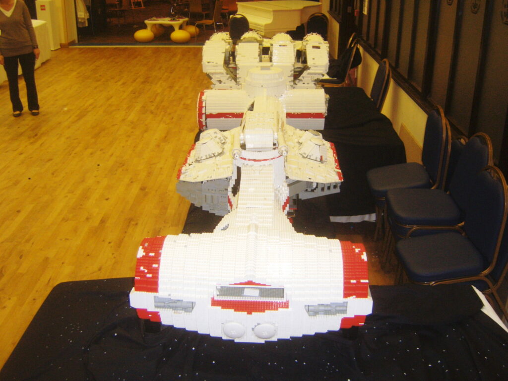
The goal of this build is to create a minifigure sized Tantive IV™ that is self supporting on its landing gears without the use of glue or non-Lego® structural reinforcement. When one looks at the ship with a critical eye, the core of the ship is a long structure from the end of the center engine (middle engine in the middle row of engines) all the way to the front of the bridge. This is a single, 3.6 m long beam supported at two points, the front and rear landing gears. The engines and the bridge portions of this long beam are cantilevered out beyond the landing gears. Regardless of design, large cantilevered sections of Lego® tend to sag, so it is important to minimize the cantilever length.
Based on the movies depictions of the Tantive IV™, it is challenging to see where the landing gears are. It is shown on the ground in “Star Wars: The Rise of Skywalker” but the landing gears not clearly visible. I have scanned other for Correllian CR90 Corvettes in “Star Wars Rebels” but have not found a planetary shots of the ships on ground with landing gears extended.
Taking this as an opportunity to locate the landing gears where they make the most sense structurally, I have chosen to locate them on the flat, sloped portion of the engines and just ahead of the front gun turrets. This should minimize the cantilever of the engines to approximately 90 studs and the bridge area to approximately about 80 studs. This will required a strong beam approximately 270 studs long between the landing gears to support a majority of the ship. Another key aspect of these locations is that they are close to the three heaviest portions of the ship – the reactor block at the rear of the ship and the body and the bridge at the front of the ship.
Another aspect of the Tantive IV™ is that it consists of several cylindrical shapes. There are a lot of options for creating cylinders in Lego®, however, the options become more limited at the larger diameters we are considering for the build, approximately 36 studs for the area around the sensor array. The focus of this post is the main structural support. Another post will look more closely at cylinders.
Structural Techniques
Lego® is defined as a “Plastic building block toy”. When most people of my generation (Gen X) think of Lego®, they think of the bricks and building houses or other buildings. Trying to construct a 3.6 m long ship using bricks is possible but challenging from a weight and corresponding strength perspective. It has been done before.
There are two main ways to approach Lego® structure:
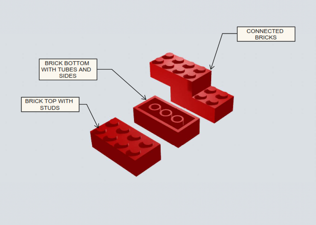
Brick: What we are most familiar with, the interlocking of Lego® Bricks to create shapes that rely on the friction of the studs on the top of the bricks to tubes and sides on the bottom of bricks to create a connection.
Technic™: The use of pins or axles to connect holes in the Technic™ bricks or beams (also known as lift-arms) together which relies on the friction of the pin in the holes of the bricks or the shear strength of the axle or pin between two bricks or beams.

Lego® by its nature is incredibly strong in compression. The nature of the material and the design of the bricks does not allow the bricks to deform and fail easily. A link to an article on that strength is shown on the right.
To overcome Lego® in tension all one has to do is exceed the friction force created between the studs on one piece and the tubes and edges on the other. In some cases when there is enough studs creating a connection, this can be a considerable force.
As outlined above, the core structural element of the ship will be a beam from one end of the ship to the other. Beams by their nature are subject to compressive forces at the top and tensile forces at the bottom. There are several types of structural beams that have been developed and each is used in different applications depending the economic and performance parameters required for that particular application.
Economic parameters are straight forward. The goal is to meet the strength requirement at the minimal cost. Cost is dictated by the type of material and the amount of it. There can be trade-offs between material. Concrete is typically less expensive than steel but steel is typically three times stronger based on unit mass so you would need less of it. This is really not a concern for us, as we have chosen our material. The applicable principal is that we want our structure to be strong enough to meet our requirements but to be be efficient in doing so to limit cost (the amount of Lego® needed to be purchased).
There are an infinite number of performance parameters for a structure depending on its use. The ship we are building is an unloaded static structure. This means that it only needs to be able to handle its own weight. There are no loads on it due to movement or vibration or external weights acting upon it. The two key performance parameters are:
- Strength: The ability for the structure to be able to handle a load without collapsing or failing.
- Rigidity or Stiffness: The ability for a structure resist deformation under a load.
A hammock needs to have the strength to hold the weight of a person in it but is also allowed to deform – stretch to accommodate that load. We do not want our ship to sag like a hammock and therefore require structural stiffness.
In the simplest form, a beam can be the trunk of a tree or a slab of rock to the most complex such as an AI optimized carbon fiber matrix. In between there are a number of classic shapes and designs. For Lego®, the focus comes down to two options which are a solid beam or a truss.
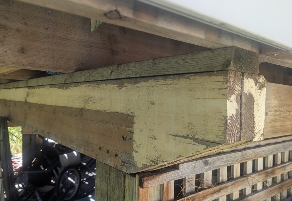
A common example of a solid beam is found in most every wood framed house and deck. It is 2 x 10 or 12 dimension lumber, laminated together and held between two posts.
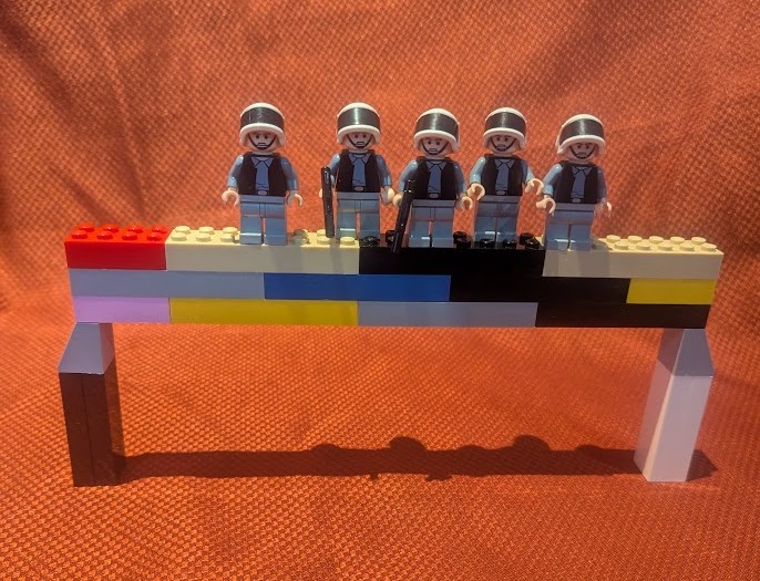
In Lego®, this can take a few different forms. It can be a series of staggered bricks. Brick beams tend to be weak unless they have sufficient dimensions that allows the bricks to be staggered in multiple directions locking everything together from multiple directions.
Another strong form of solid Lego® beam is staggered plates that are stood on edge. This is similar to a brick beam but studs are oriented vertically as opposed to horizontally. This orientation and the increase in the number of studs holding the pieces together lead to much stronger beams even though the overall size is smaller and it is lighter. The plates on edge act like the laminated 2 x 12 deck beam above.
A truss by definition is an assembly of beams. The beams are typically oriented into as series of connected triangles that together form a larger beam. Lego® trusses are easiest to make from Technic™ bricks and beams along with pins. The challenge of Lego® trusses is that Lego® has very specific geometric limitations. Triangles in Lego® trusses have to follow Pythagorean geometry for the diagonal members to line up with the holes in the Technic™ bricks.
The example above is a 8-9-13 triangle which is not exactly Pythagorean triangle but is very close. Note that the measurements for the length of each side are from the center of the holes or pins. Back to elementary school geometry we all remember that the Pythagorean Theorem is:
A2 + B2 = C2
A and B being the two short sides of the right-angled triangle and C being the hypotenuse or long side of the triangle. In this case:
A2 = 8 x 8 = 64, B2 = 9 x 9 = 81,
C2 = 64 + 81 = 145
Therefore C = 12.04. There is a slight tolerance in Lego so in this case a 13 long beam – 12 long from center of pin to center of pin works.
Other useful triangles for Lego® trusses are 4-7-8 (16 + 49 = 65, 8.1) and 9-12-15 (81 + 144 = 225, 15)
Optimization
There is a decision to be made between the plate beam on edge and the truss for the structural design. After some testing and research, the truss is the better option from a strength and cost perspective. It is lighter per unit of strength and more cost efficient from a part perspective.
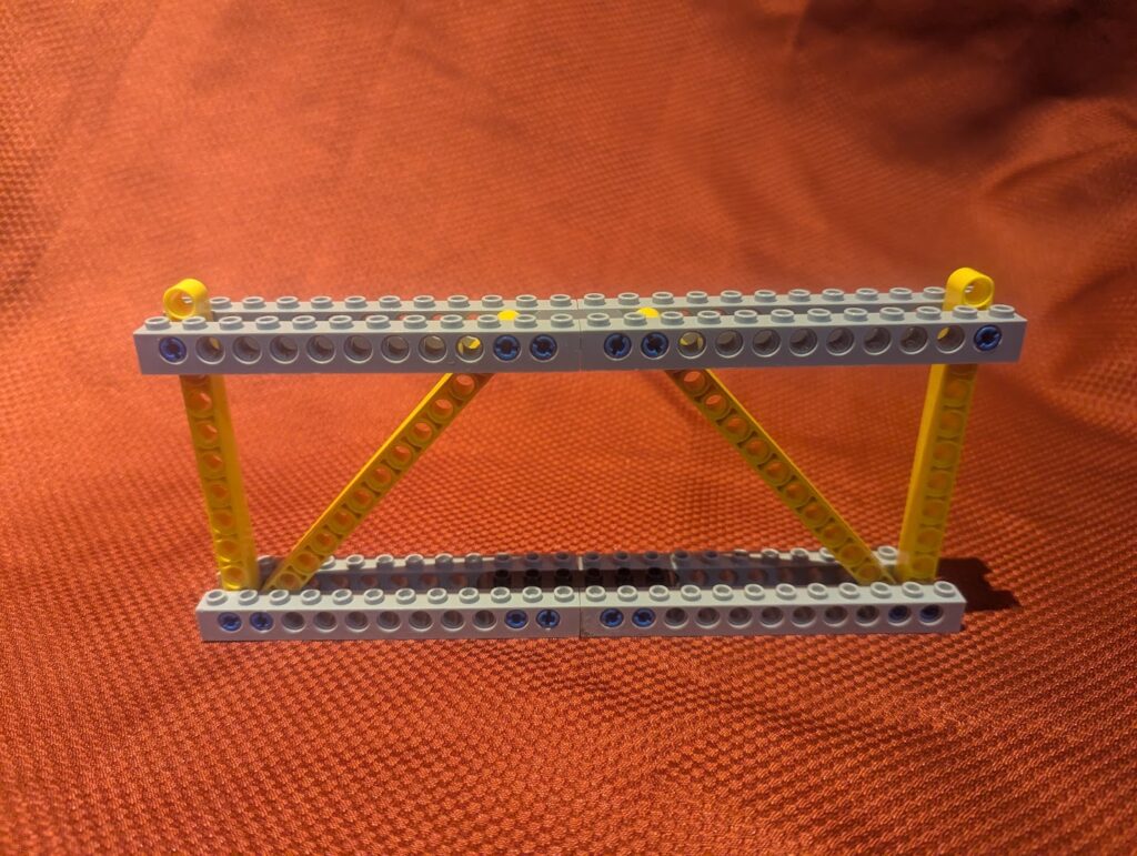
Settling on a truss, the next step to define the type and design. Truss types are differentiated by the direction of the diagonal members. The truss in the picture above is a Warren Truss. When loaded, the different orientations of the diagonals will result in different truss members being in compressions or tension. Different materials respond in different ways to compression or tension so depending on what material was available to construct the truss, the most efficient design could be chosen.
For our design, the diagonals are all the same size and material – Technic™ beams – so the configuration is less of an issue to maximize structural efficiency. What is important is our second performance parameter – stiffness. The Long Truss which is characterized by crossing diagonals in an X pattern between vertical beams is the stiffest design with the lowest defection. It has one more diagonal than most truss designs but this additional component also reduces the load on other components and contributes to the overall strength. This will be the design for the main beam through the center of the ship.
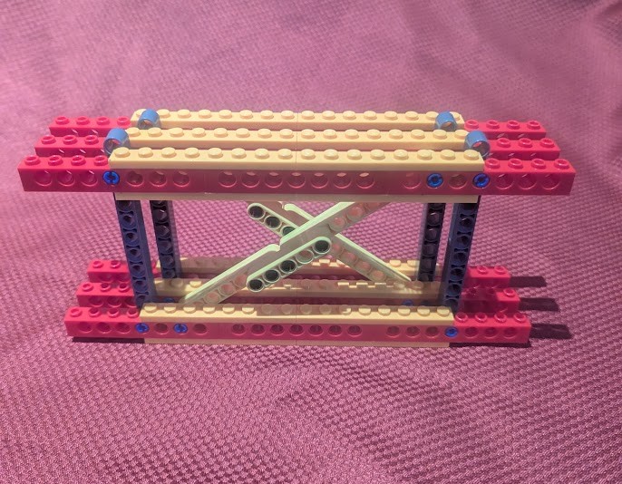
Some things to note about the above Lego® Long Truss design above:
- It uses the Pythagorean triangle dimensions 9-12-15.
- The chords (top and bottom beams) are made of 1 x 8 Technic™ bricks. Reviewing the price of 1 x 8 Technic™ bricks reinforced by 1 x 8 plates is the most economical.
- In order to create 16 long beam for diagonals, a 9 long beam has been connected to a 7 long beam with a 5 long beam and pins. Beams longer than 2 only come in odd number lengths.
- The vertical beams protrude 1 above the top chord as these are 11 long beams and only 10 long is required.
- The top and bottom chords look very large with 3 rows of bricks. They have to be.
- For a distributed load along this truss, the top chord will see the highest load which will be in compression.
- The bottom chord will see a reduced load but it will be in tension and Lego is weaker in tension thus more elements to carry the load are required.
- One mode of failure is the pull out of the pins from the Technic™ bricks.
- The sandwich design with the 3 long pins holding the vertical and diagonal beams between bricks divides and stabilizes the force on the pins and prevents pull out.
- It is unlikely the pins will shear as they have significant strength in this configuration.
- The reinforcing of the top and bottom of the Technic™ bricks with 1 x 8 plates strengthens the thinnest and weakest part of the brick preventing failure by deformation of the holes.
- The truss can be expanded and built to any length.
- The truss can be doubled or tripled-up to create stronger sections where required.
- Using pin connections, the truss is difficult to pull apart in the vertical and longitudinal direction unlike a simple brick connection that relies on friction. It can be pulled apart in a transverse direction but the placement of a plate across all three bricks would prevent this.
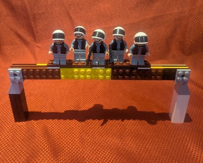
Here is a quick strength test of the beam. There is no noticable deflection and no weakening of any of the Lego beams, bricks plates or pins.
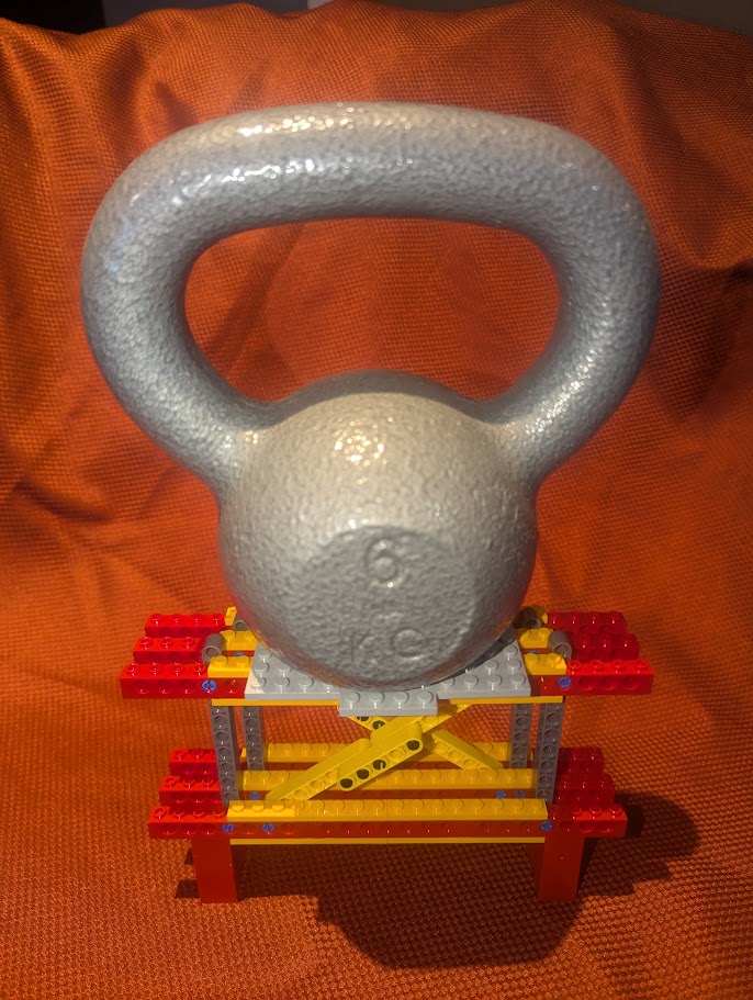
Thank you for reading this post. Stay tuned for more as the structure goes beyond just the main support truss.