
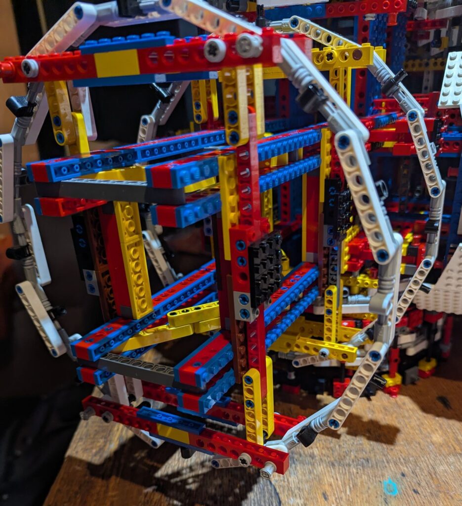
The cylindrical part of the Tantive IVTM between reactor block and the main hold area of the ship with the escape pods presents the most technically challenging part of the build. A significant number of revisions have been required to continually improve the strength and look of the ship in this area.
This post addresses the complexity of creating large circles and cylinders in Lego. Lego produces a 6 stud diameter cylinder. Another option is to use round bricks. The largest readily available are 4 x 4 corners when connected produces an 8 stud cylinder. Adding bricks between the corners the cylinder can be expanded but starts to loose it round shape. There are 12 x 12 and 16 x 16 round corners as well but these are fully filled and thus only really useful as base plates.
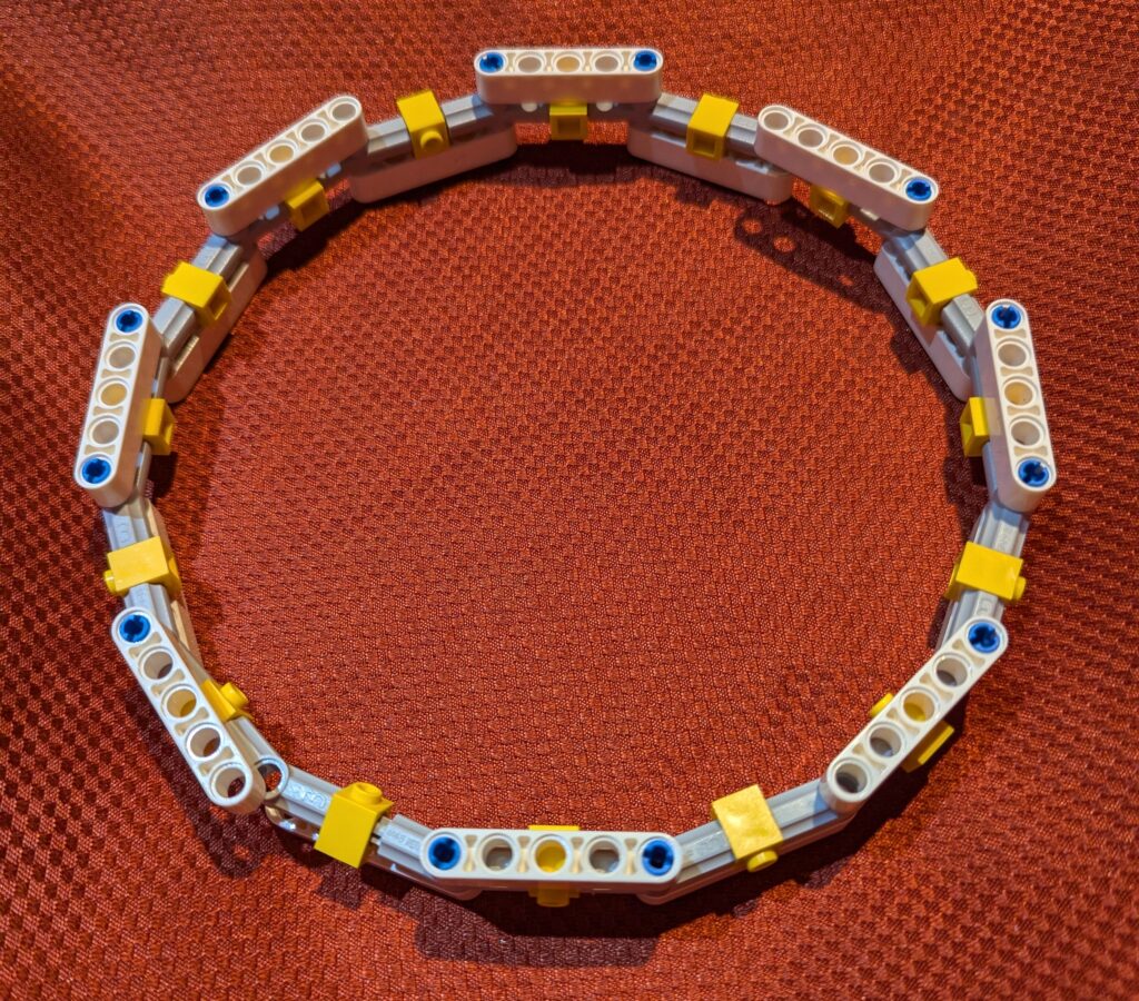
Looking at what is available in Technic parts, I was drawn to the Angle Connector #3, Part 32016/42128. This has an internal angle of 157.5o. When 16 of these are connected, it creates a 16-sided polygon known as a Hexadecagon. The angle connectors are designed to be used with axles. They also have a pin hole at the inflection point.
These connectors were used in Set 75191, Jedi Starfighter with Hyperdrive [ring]. 5L (5 studs long) axles were used between the connectors, 3L pins were placed in the connectors and 7L beams (lift-arms) were placed over the pins. This combination of axles, pins and beams between the connectors creates a very solid but some what flexible ring. The diameter of this ring from the center of beam to center of beam is 30.16 studs. The set added plates to the outside of the ring but there were gaps between the plates because the bottom edges of the plates were at a diameter of 32.16 plates. This results in a perimeter of 102.4 studs which when divided by 16 results in each side being 6.4 studs long. The set uses 6 stud plates on each side thus there is a 0.4 stud gap between each side of the ring.
For the cylindrical portions of the Tantive IVTM to look like it is cylindrical, there should be minimal gaps. Starting with the 36 stud diameter determined in my scaling calculations (see my post on scaling) we can do some quick calculations. A 36 stud diameter hexadecagon results in each side being 6.96 studs – close enough to 7. Modelling this diameter in LeoCAD, shows that the 7 studs per side is a little chunky. Increasing the sides to 32 (an Icosidodecagon), the sides drop to 3.42. Alternating between 3 stud wide and 4 stud wide sides, this shape looks very cylindrical and there are minimal gaps.
There are other diameters required for the ship. The communication section with the dish is slightly smaller. Using #3 connectors and scaling back from 5L axles to 4L axles between them and using 7L beams and beams to connect the 6 stud lengths between connectors provides a circle with a diameter creates a circle with a diameter of 30.16 studs and sides of 6 studs. This 6 stud difference from the 36 diameter main cylinder looks good and is close to the 28 stud diameter calculated from scaling exercise.
The engines are another cylinder. Extending my work above, I used 3L axles and 5L beams to create a 16 sided circle that is 25.28 studs in diameter and 79.42 studs in circumference – close enough to 80 studs. When scaled the engines are about 7 m in diameter which equates to 25 studs at minifig scale so this circle and resulting cylinder is very close to the requirements. Each of the 16 sides is 5 studs wide.
Connecting all of these rings and cylinders to the main structure (see previous Structural Post for a discussion of the main structural beam of the ship) of the ship is a little complex. The rings are generally have even numbered diameters and the structures have odd stud widths and more complex height dimensions. I have used 2 constructed beams that connect to the main structural truss and to the pin holes in the connectors on the rings. Placing of these beams on each side of the ring and inserting an axle through the connector, ring beams and connection beams creates a solid connection.
To get the constructed beam the correct length requires the use of 1×2 Technic Bricks with 2 holes (Part #32000) to create 1/2 stud off-sets. It took some experimentation with different configurations to get a stress free connection between the structural trusses and the rings. These connections are not perfect. Due to the offsets, the rings are generally not centered, being off by about 0.25 of a stud. Similarly there is about a 1/6 brick height bust in the vertical part of the connection. The pinned set of beams allows a little flex to compensate for this. I have continued to refine the connection over the course of the build but have not found the perfectly dimensioned connection yet.
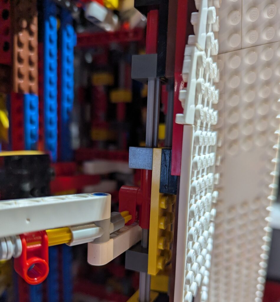
Once the rings are in place on the main structural trusses, it is time to create a connection system for the plates that will form the outer hull of the ship. Originally, I worked with 1×1 technic bricks (Part #6541) inserted on the axles between the connectors on the rings (as seen in the engine ring above) and ran plates connected to these between the rings. I found that this did not create a strong connection or provide a rigid outer structure. Due to the minimal number of studs available to connect the plates, the plates fell off and it was challenging to keep all the outer hull rigid and plates aligned.
Drawing on some aerospace references I found that axles would provide an inexpensive and rigid frame to which the hull plates could be connected. These longitudinal axles are analogous to those used on airplanes to provide rigidity along the hull of the plane and are called “longerons”. They also allowed for the further use of connectors that allow for pinned connections between the rings and axle/outer hull structure. This is a superior connection that utilizes the cross block 90 degree 1×2 axle/pin connector (Part 6536/40146) .
The axle longerons are in a firm orientation compressed by the rings. This allows 1×2 Technic bricks (Parts #3700 and #31493) placed on the axles on intervals to connect plates to and the outer hull on top of that.
The truss, ring and longeron structure is very robust and I do not anticipate too much sag as it is also lightweight. The 36 stud diameter, 32 sided ring has an internal area of 3980 studs. At the ring connection which is the most dense part of the structure, there is about 800 studs, so about 80% of the structure is void at this location. Between the truss/ring connection points, the density is less than this. This low density design is light weight and critical to structural stability, efficiency and cost.